|
Signal converters are signal conditioners plus a processing unit to further simplify operations. Ultrasonic Signal Converters are composed of a processing unit, driver and an amplifier. The driver boosts power to fully excite the sensor. The returning echo is filtered, clamped, amplified and made available on an output wire. The illustration below shows the basic building blocks of the Hexamite Ultrasonic Signal Converters. Input is fed through a capacitor and clamped before it is conditioned for amplification. Amplification is typically about 1000 and the signal is made available at the output through a capacitor. The device has a processing unit, to further simplify applications
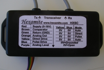
The following illustration shows how the Hexamite signal conditioner can be utilized. A pulse of amplitude greater than 2.5 volts can be applied to the blue wire. The processor will for the duration of the pulse, transmit a train of pulses at a frequency specified for the signal converter. Alternatively the blue wire can be grounded or connected to the green wire, in this case the user can send a specific form of pulse train through the yellow wire. Typically 20 to 40 pulses are required to excite the sensor fully. After the pulse train has entered the Power Boost Driver, it may be necessary to wait a few milliseconds for the result from the pulse train to be echoed back to the sensor. The sound travels approx. 344m/s hence if the surface creating the echo is 10 m away, it will take the signal about 60 mS to travel to the surface and back. Therefore train pulse repetition should not exceed 16 times per second. Below the RX and the TX lines are connected together, here the transducer is a single transceiver. The excitation is about a million times more powerful than the echo that needs to be detected. It can take some time for the sensor to settle after excitation, typically a few milliseconds.
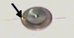
Connecting a Miniature Sensor Connecting a miniature sensor to the signal converter needs to be done with care. The wire extending from the soldering point indicated by the error on the image to the right, needs to be connected to the shield. The other wire is connected to the core of the coaxial cable coming from the signal conditioner. Connecting the Canned version This is fairly easy. Connect the pin that is soldered to the can to the shield, and the other pin to the core. Connecting other sensors Other sensors have shielded cables extending from the back. The connection is straight forward, connect the shield to the converter shield and the core to the converter core. WARNING if the device is reverse polarized or if the Absolute Maximum Ratings are violated, device can be damaged.
|
|||||||||||||||||||||||||||||||||||||||||||