Hexamite

Ultrasonic Position Scanner 4 by 4 channels

Main Index

The ultrasonic position scanner is designed for high speed high resolution complex motion monitoring, it can be used with hexamite 40khz ultrasonic transceivers, and miniature button sensors which may be glued on objects by application of a double sided sticky tape.

Application

  • Multidimensional Multipoint Positioning
  • Complex Motion Monitoring .
  • Low Cost Animation Aid
  • Applicable in air and water, gasses and liquids
  • position feedback for robots

Features

  • Super High Resolution 0.09mm
  • Range 5.5 meters 
  • High Repeatability
  • Modular Construction
  • High Position Sampling Rates  

Hx740-4x4 ultrasonic position scanner 

Hx740-4x4 is a simple transmission source to receiver time of flight measuring device. The simple networking scheme allows many scanners to be chained together to form a multipoint positioning array. Each device has 4 transmission source channels and 4 receive channels, this yields a 4x4 positioning array or a total of 16 positioning points. This may be adequate for many applications, but if two Hx740-4x4 scanners are networked together a 8 by 8 positioning array can be created. If three Hx740-4x4 scanners are networked together, a 12 by 12 positioning array is created consisting of 144 points of positions. The Hx740-4x4 can utilize the HE240TR, HE240TX, HE240RX, HE240STX and HE240SRX. It can also utilize the miniature button types like the HE240TR-B and etc. The sensors are connected to a miniature coaxial extension from the scanner, connecting the sensors to the scanner is a simple procedure. There are two threaded internal spacers for 3mm screws on the back of the Hx740-4x4, to facilitate mounting on panels or walls. The size of the HE740-4x4 is 78 x 148 x 32 mm or 3.1 x 5.8 x 1.26"

Network Chaining 

The figure on the right shows how multiple scanners can be chained together to form a single system. Four devices chained together will enable acquisition of a 16 by 16 positioning array containing a total of 256 positioning points. 

Sampling Rate

The scan updated time T per transmission channel is governed by the following relationship:

T  =  K + N * 210/Baud rate

Where K = 17 milliseconds and N is the number of scanners linked on a network. 

Communication delay for a baud rate of 19200 is 210/baud rate or 11mS, and for a baud rate of 115200 this delay is 1.8 mS 

Using 19200 baud for reference, the total delay for a single scanner is 17 + 11 ms or 28ms this equals 35 updates per second. Each update or scan  includes four positioning points, so the total number of positioning points per second are 4/28ms. This equals 140 position points per second (pp/S), shared by N number of transmitters. For a two scanner system, scan update delay becomes 17+22 ms or 39 ms. Since two scanners have four receivers each, each scan contains eight positions in this case the scan rate becomes  8pp/39ms  =  205 pp/S (positioning points per second). The tables below shows overall scan rate for various setups.

Baud rate 19200, communication delay 11ms

transmitters 4 receivers 8 receivers 12 receivers 16 receivers
1 140 pp/S 205 pp/S 240 pp/S 262 pp/S
2 140 pp/S 205 pp/S 240 pp/S 262 pp/S
N 140 pp/S 205 pp/S 240 pp/S 262 pp/S

Baud rate 115200, communication delay 1.8mS

transmitters 4 receivers 8 receivers 12 receivers 16 receivers
1 212 pp/S 388 pp/S 535 pp/S 661 pp/S
2 212 pp/S 388 pp/S 535 pp/S 661 pp/S
N 212 pp/S 388 pp/S 535 pp/S 661 pp/S

pp/S means positioning points per second where each positioning point is represented by a 16 bit hexadecimal value. It is important to note, that for example a system consisting of two transmitters and four receivers  yielding overall scan rate 212 pp/S must share these points between the two transmitters. Therefore each transmission channel has 212 / 2 or 106 position points every second. Hence the number of positioning points associated with each transmitter per second becomes (overall scan rate / N) where N equals the number of transmitters.

Network Wiring

Hx7xx-4x4 logic symbol

Changing the Baud Rate

If the blue mode wire is either at 5Vdc or open the device will allow the baud rate to be changed. The new baud rate is only applied while the blue wire is connected to ground. If an ESC followed by ASCII character A, B, C, D, E, F or G is transmitted to the Hx740 the baud rate is selected as shown in the table on the right

If the Blue wire is not grounded during boot or startup the Baud rate will be reset to 19200 and it will be necessary to re-enter the desired baud rate.

ASCII char. Baud Rate
A 2400
B 9600
C 19200
D 28800
E 57600
F 76800
G 115200

Software Configuration

The Hx700 series can be configured through it's serial port, it can be manipulated by and connected directly to a personal computer. Each device has a primary address and a secondary address. The secondary address is always the primary address + 1, the primary address is always an even number, and the secondary address is always an odd number. All broadcasted data is hexadecimal  but addresses and commands received by the devices are binary. Addresses are in the range from 71 to 255, and commands (control characters) from 0 to 48. Characters are ignored unless these directly apply, like ' carriage return ' (13), the character ' - ' (45), the character 'esc' (27) and own address. The character ' - ' ( 45) is interpreted by the devices on the network as a synchronization signal.

Control Characters  decimal  hexadecimal

HPD interpretation

Carriage Return 13 0D This will force the master device to transmit a synchronizing hyphen, and initiate a new position acquisition cycle for all devices on the network. 
Escape 27 1B BREAK! This will force all devices to be ready for commands.
hyphen ' - ' 45 2D The device enters position acquisition cycle.


Scanner Control Parameters

If the Blue mode wire is grounded, then six bytes from EEPROM permanent memory are copied to the working registers of the Hx700 series. These six bytes are the parameters that control the program. The user can change these parameters via the serial port of the Hx700, and thereby modify the operation of the device to suit most operating conditions. If the blue mode wire is open during startup, the device will load it's default values into the working registers. 

Byte No. What the Byte does Default value
1 Sets reverberation and transmission control 44 hex
2 Termination byte and Network control 0D
3 Inhibit Receiver 1 02
4 Inhibit Receiver 2 02
5 Inhibit Receiver 3 02
6 Inhibit Receiver 4 02

Byte 1: Reverberation and Transmission control (RTC)

Reverberation: happens when the sound continues to bounce around after the sound source is no longer emitting. Extreme reverberation occurs, when the sound bounces of materials that reflect the sound nearly 100% inside enclosed perimeter. Eventually molecular relaxation will suppress the sonic activity. The reverberation control, ensures the user will be able to adjust for even the most extreme cases.

X in the table means DON'T CARE

Higher Significant Nibble
RTC extra time RTC extra time
0X 0 8X 64mS
1X 8mS 9X 72mS
2X 16mS AX 80mS
3X 24mS BX 88mS
4X 32mS CX 96mS
5X 40mS DX 104mS
6X 48mS EX 112mS
7X 56mS FX 120mS

The Hx700 series interpret the first byte as two nibbles. I.e. instead of eight bits, the byte is read as two times four bits. The higher significant nibble sets the 16 level reverberation control, changing this data will change your sampling rate). Every level adds an extra time to the scan update time T as follows  

The lower significant nibble is used 
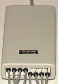
to select the number of transmitters scanned. If many scanners are ganged together via network, the lower significant nibble of all scanners must be the same; and represent the total transmission channels scanned through all the devices. Since one nibble only counts to 16, the largest size positioning array achievable with the HE700 series is 16 by 16 or 256 positioning points in total. This can be expanded upon request.

Byte 2: The termination byte

If the termination byte of device 'X' is the primary address of device 'Y' on the same network, then device, 'Y' will be prompted to transmit it's position acquisition result once device 'X' has completed it's transmission of it's results. { IF (the last device in the chain has a termination byte 'Carriage return')  THEN the position acquisition cycle is repeated indefinitely with very high sampling integrity }. The chain is started by the hyphen transmission of the master device, and restarted by the carriage return of the last device on the network. The device with the (numerically) lowest primary address is always a master, the rest of the devices are slaves.

If the Hx700 is not networked and there is no device to restart the acquisition cycle. This byte should have the decimal value 33, hexadecimal value 21 or ASCII character "!". If the termination byte has this value the Hx700 automatically restarts the acquisition cycle.

Byte 3: The receive inhibit bytes

The receive inhibit bytes, allow further control to maximize the performance of the device. This control is instrumental in both noise reduction, and in case there is a reverberation problem. Adjusting this byte may relinquish the need to introduce a reverberation delay. If the object which distance is being measured, never comes very close to any of the transmitters; then there is no need to be listening for signals in time space where it will can never exist. In other words the receiver isn't enabled until there is a reason to belief a signal will happen. For optimum performance the value in this byte should be as high as possible, but lower than so as to inhibit acceptable operation. It is up to the user, to experiment with this value to see how it serves in each situation. This byte can have any value between 0 and 255 or 0 and FF hexadecimal. When set 0 then this byte doesn't do anything, but at higher values it begins to take an effect.


Interface cable Wire Colors and Function

The Brown Wire: If the brown wires of all the Hx700 scanners are connected together, the scanners are networked. A single device connected to an RS232 port will give the PC access to all the devices that have brown wires connected together. 

The Blue Wire: If the scanner is started up while the blue wire is open or connected to 5 volts, the device will operate using Default parameters. If the scanner is booted with the blue wire grounded or at 0v, the device will operate using EEPROM or User Parameters. While the blue wire is open or high (5Vdc), the user can change the scanner's baud rate. The change is only valid if the blue wire is grounded during boot.

The Black Wire: is the serial transmission or TX of the Hx700 series. Levels vary from 0 to 5 volts, compatible with most PC RS232 serial ports. This wire should be connected to the RX input to the PC or pin 2 on a DB9 connector. 

The White wire: is the serial input of the device, PC RS232 serial port compatible, this wire should be connected to the TX out from the PC or pin 3 on a DB9 connector. In case many Hx700 series scanners are linked together via the brown wire, the white wire of all scanners except the one connected to the PC should be grounded to avoid a small possibility of noise interruption.

The Orange Wire: The voltage level applied to this wire should be between 7 and 16Vdc. The transmission voltage to the sensors is proportional to the voltage on this wire. Care must be taken that the voltage to the sensors is with in specified limits.

The Green Wire: Ground or Return

!!! CAUTION !!!

Do not apply a potential higher than 7V to the Brown wire or the Blue Wire
Do not apply a potential lower than -0.3V to the Brown wire or the Blue Wire

A current higher than 20mA forced through the Brown wire or the Blue wire may damage the Hx700.

The transmit signals t1, t2, t3 and t4 are proportional to the voltage supplied to the Hx700. If the HE240TR or HE240TX are used make sure the transmit drive signals to the ultrasonic sensors don't exceed 100Vp-p. Either the supply voltage must be adjusted or a voltage divider must be used to ensure the voltage applied to the sensors never exceed the maximum. This maximum is only 42V peak to peak for the HE240TXS or HE240TRS. If the transmission signal exceeds this limit the sensitivity of the sensors is gradually diminished and both range  and position sharpness is degraded.

Application Considerations for sealed sensors ONLY

If the HE240TR, HE240TX, HE240TRB or HE240TXB is used the configuration below is NOT NEEDED.

If the HE240STR or the HE240STX is being used to transmit the sonic wave, the voltage V supplied to the sensor must not go higher than 42V peak to peak for sustained periods. The illustration on the right shows a voltage divider used to protect the sensor. The voltage V becomes 

V = V(he860) x R2 / (R2+R1)

The values for R1 and R2 should be selected so that the voltage V stays beneath 42V peak to peak. If the voltage V exceeds this limit the sensor gradually degrades, this is generally a slow process depending on the level of limit violation. For no degradation to occur the voltage level must stay within 42V peak to peak.

A single resistor R1 between 0 and 10k ohm can be deployed in series may be adequate omitting  R2.

Main Index

Copyright © 1999 [Hexamite]. All rights reserved.
Revised: December 16, 2016 .

More Information